
When the 'Cold Spot' Can Sometimes Be The Issue in Electrical Systems.
- Feb 2
- 7 min read
Updated: Mar 9

In the world of electrical maintenance, most professionals learn early on that heat is the enemy. When a connection begins to fail, resistance increases—and with resistance comes temperature rise. This is why thermal imaging has become one of the most powerful tools in predictive and preventative maintenance programs across industrial, commercial, and institutional power systems.
Under normal circumstances, a high-resistance electrical fault shows up as a hot spot on an infrared camera. The hotter the component compared to its surrounding equipment, the higher the likelihood that the conductor or connection is degrading, loose, dirty, oxidized, or improperly torqued. It’s a simple equation:
High resistance + current = heat.
But in more complex installations—especially systems with parallel conductors—thermal patterns don’t always follow the rules we expect. In fact, sometimes the most dangerous conductor in a system isn’t glowing white-hot… it’s actually cold.
This blog post explores a real-world case from one of our recent thermal imaging inspections, demonstrating why a cold conductor in a parallel run can be a major red flag. We’ll walk through what happened, why it matters, and how facility managers can prevent costly failures by understanding the underlying electrical principles.
The Real-World Discovery: A Parallel Run That Didn’t Add Up
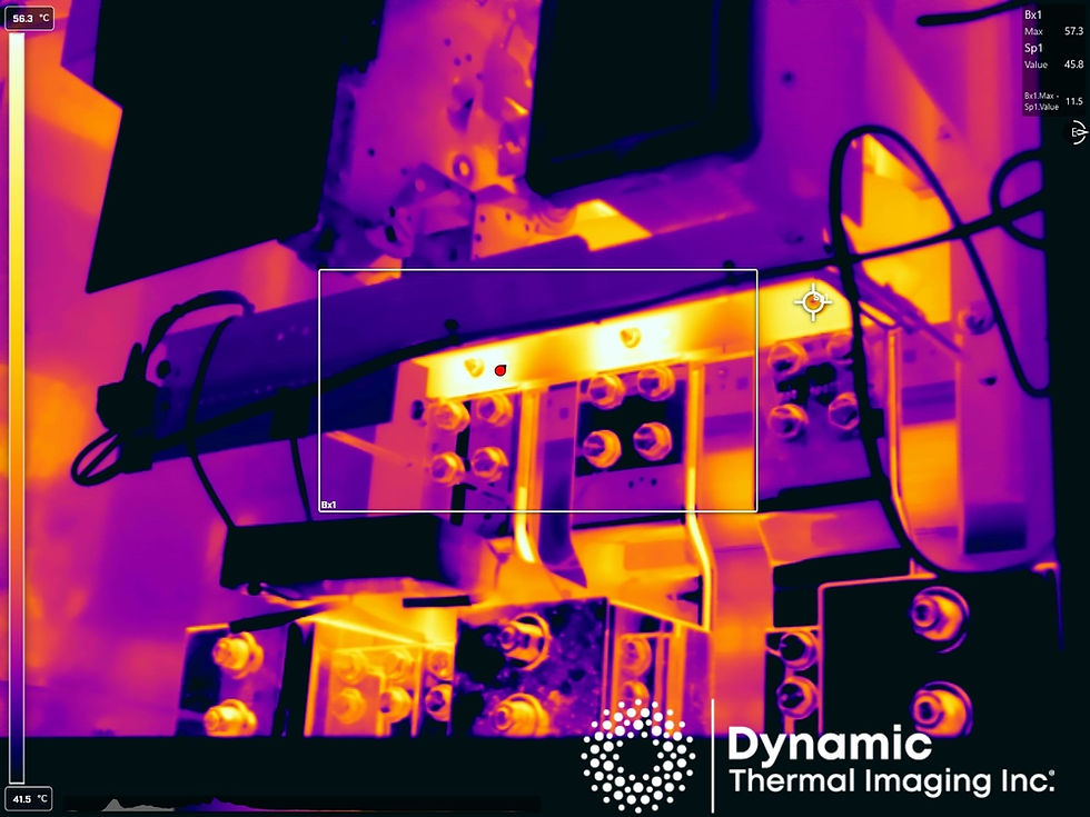
During a routine infrared inspection, one of our thermographers spotted what seemed to be a straightforward issue: a hot spot on one of two parallel conductors on C Phase.
At first glance, this looked exactly like thousands of other loose-connection discoveries. One conductor showed an elevated temperature, so naturally the assumption was:
“We have a loose or high-resistance connection on that cable lug.”
But something didn’t sit right.
When our technician zoomed in and analyzed the image more closely, he noticed something unusual—the other conductor on that same phase was significantly colder than expected.
That observation triggered a deeper investigation.
Here are his notes from the field:
“We originally found a high temperature on one of two parallel connections on C phase, which led us to believe it was a loose connection. When analyzing the photo further, we discovered that one of the parallel conductors on the C Phase was colder than the other. The amperage on C Phase combined was ~734A. When taking the individual current readings of each conductor, one conductor was ~85A, and the other ~650A. This would mean that the 'cold' wire would have a high resistance somewhere along the line, so that the large current flow on the other conductor will choose the path of least resistance. This is a significant issue and should be rectified soon.”
This note highlights something every facility operator using parallel conductors should understand: A cold cable in a parallel run can be a symptom of dangerously high resistance.
What Should Have Happened: Balanced Current in Parallel Conductors
Before examining the problem in depth, it’s important to understand how parallel conductors are supposed to work.
When conductors are installed in parallel—either because of long distances, high current loads, or design constraints—the goal is for each conductor to share the electrical load evenly. If two cables are run in parallel on a phase, each should carry roughly half the current.
In our case, the total current on C Phase was:
734 amps
Ideally, this should split something like:
Cable 1: ~367A
Cable 2: ~367A
But when our team clamped each conductor individually, the readings told a very different story:
Cable 1: ~85A
Cable 2: ~650A
This imbalance is severe.
One conductor was overloaded by nearly 300 amps, while the other was barely conducting more than a residential stove circuit. That imbalance alone is enough to damage insulation, accelerate conductor fatigue, and strain upstream equipment.
But the real question is this: Why would one conductor carry so little current?
This is where basic electrical theory explains the anomaly.
The Principle Behind the Problem: Current Takes the Path of Least Resistance
In electrical systems, current doesn’t split evenly just because two pathways exist. Instead, it divides based on the relative resistance of each path.
Think of resistance like road conditions:
A smooth, wide, freshly paved highway (low resistance) handles most of the traffic.
A narrow, bumpy, obstructed road (high resistance) sees only a trickle of vehicles.
The same is true in parallel electrical conductors. If one conductor suddenly has a higher resistance—due to corrosion, a loose lug, a broken strand, internal damage, insulation degradation, or mechanical stress—the current will shift heavily to the other conductor.
This is exactly what happened in our real-world case:
The cold conductor had increased resistance somewhere along its run.
This resistance prevented current from flowing through it.
The current was forced into the remaining conductor, which now carried nearly the entire phase load.
When that happens, only one conductor heats up—the overloaded one.
Meanwhile, the conductor with the actual problem stays cold because almost no current is flowing through it.
Why a Cold Conductor Can Be More Dangerous Than a Hot One
At first glance, the cold conductor might seem harmless. No heat, no problem, right?
Wrong.
A conductor that is cold due to high resistance is a silent hazard. Here’s why:
1. The true fault may be hidden from the infrared camera.
Thermal cameras detect heat, not electrical conditions. If the conductor isn’t carrying current, the damaged point won’t heat up—and the camera won’t see it.
Meaning:
You may be looking directly at a failed connection and see nothing.
2. The healthy conductor becomes dangerously overloaded.
In our case, one conductor was carrying 650 A—nearly the full burden of the load.
Depending on the cable size, this can:
exceed insulation temperature ratings
degrade copper or aluminum over time
increase the probability of a catastrophic failure
lead to nuisance tripping of upstream breakers
accelerate aging of switchgear and bus duct
3. The imbalance can cause harmonics, heating, and stress on the entire system.
Uneven phase loading wreaks havoc on:
transformers
distribution panels
MCCs
switchboards
VFDs
generators
Electrical equipment is designed with the expectation of balanced loads. Extreme imbalance shortens lifespan dramatically.
4. The actual high-resistance point may worsen until it becomes a fire hazard.
Even though the conductor is cold during the inspection, the resistance point is still a fault. If that cold conductor suddenly begins carrying load again—especially under inrush or emergency conditions—the high-resistance joint could overheat rapidly.
This scenario is responsible for many electrical fires in North America each year.
How the Technician Identified the True Problem
This discovery was the result of a combination of:
Infrared scanning
Load measurement
Electrical theory
Field experience
What This Means for Real-World Facilities
Imagine an industrial facility running two 600-volt feeders in parallel to support a major production line. These conductors power motors, compressors, conveyors, and automated equipment that must operate continuously. Everything seems fine—lights are on, motors are running, production targets are being met. But behind a closed door in an electrical room, a dangerous imbalance has been slowly forming.
Phase 1: The Beginning of the Problem
Months earlier, during routine work or vibration or thermal cycling, a lug on one of the parallel conductors loosened just enough to increase resistance. Not enough to trip a breaker—not enough to cause immediate overheating—but enough to alter how current divided. The fault began silently.
Phase 2: The System Compensates
Electrical systems will always try to balance themselves. When one path becomes harder to travel, electricity favors the easier route. So more and more current shifts into the healthy conductor. Operators don’t see or hear anything wrong. The equipment keeps running.
But the insulation on the overloaded conductor begins to age faster. Its operating temperature creeps upward.
Phase 3: The Thermal Imaging Scan
During a scheduled preventative maintenance shutdown, a thermographer scans the switchboard and notices a bright, hot conductor on C Phase. He flags it for further nvestigation. Then he notices something else:
The parallel conductor beside it is unusually cold.
That’s the red flag that triggers deeper testing.
Phase 4: Measuring the Load
The technician clamps each conductor and discovers the imbalance. Instead of sharing the load, one conductor is carrying almost the entire 734 amps of current.
Phase 5: Escalation and Repair
With a clear diagnosis, the facility takes corrective action:
de-energizing the equipment
cleaning or re-torquing connections
replacing damaged lugs or conductors
analyzing upstream equipment for thermal stress
re-testing the system for proper load balance
In this case, a catastrophic failure was prevented.
Why Thermal Imaging Alone Isn’t Enough
This case illustrates something many people misunderstand about thermal inspections:
Thermography doesn’t find electrical problems—thermographers do. Hire a thermographer with electrical experience.
An infrared camera is a powerful tool, but it only sees surface temperature differences. Without the context of load readings, electrical theory, and field experience, this problem could have been misidentified.
A less thorough approach might have:
retorqued the hot connection
left the cold conductor untouched
allowed the high-resistance point to worsen
And eventually, the cold conductor could have failed catastrophically—without ever having been visibly hot during an inspection.
This is why you need experienced technicians interpreting the data—not just pointing a camera.
How to Prevent This Issue in Your Facility
Parallel conductor failures are more common than most people think. To avoid them, facility managers should:
1. Conduct annual thermography on all major electrical equipment
Infrared inspections should focus on:
switchgear
MCCs
bus duct
distribution panels
transformer connections
parallel feeders
VFDs
2. HIRE PROFESSIONALS!
A thermograpger without electrical credentials would need to be very smart to catch this problem. An electrician that does thermography as a side-hustle might not find this catastrophic issue. Hire real, professional, electrical thermographers with electrical credentials.
3. Ensure maintenance staff understand how parallel loads behave
Misdiagnosis is common without training.
4. Install torque markings and perform periodic re-torquing
Thermal cycling and vibration loosen connections over time.
5. Track trends over multiple inspections
A single snapshot is good—trend data is better.
6. Take immediate action when load imbalance is found
Ignoring the problem accelerates equipment aging and increases risk.
Final Thoughts: What This Case Teaches Us
This real-world thermal imaging case is a perfect example of why electrical maintenance is both an art and a science.
Most of the time, a hot spot is just a loose connection. But sometimes, the real culprit isn’t the conductor that’s glowing—it’s the one that’s unexpectedly cold. This case reinforces several key lessons:
Parallel conductors must carry similar loads.
A cold conductor can indicate high resistance.
Load readings are essential to diagnose thermal anomalies.
Overloaded conductors can silently approach failure.
Skilled interpretation matters more than the camera itself.
Electrical systems don’t always behave intuitively. That’s why predictive maintenance—powered by thermal imaging, electrical testing, and expert analysis—is essential for preventing downtime, equipment damage, and safety hazards.
If your facility uses parallel conductors, large feeders, or high-load distribution systems, this is exactly the kind of issue you want to catch long before it becomes a major outage.


Comments